- Gateways and connecting lines determine the sequence of activities. Current state and Future state process models can be created and managed in Enterprise Architect. The diagrams can be organized into a process hierarchy allowing drill down from high level to lower level diagrams.
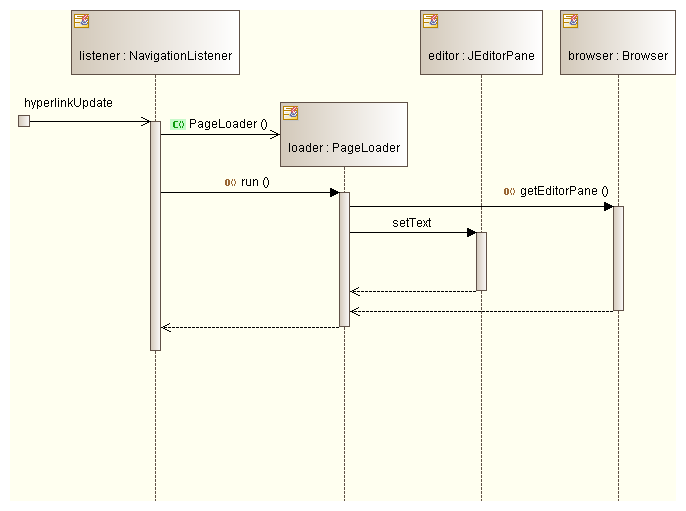
- Construction of sequence diagrams in real-time in Enterprise Architect 9 Introduction This text show how in just a few steps one may generate a sequence diagram in a running application. JAVA application, which enables building a contact book, is used an example. What will you learn: After having read this tutorial you will.
- Aug 17, 2017 A Composite Structure diagram provides one convenient way to create a Class, Part, or Port. Class, Part, and Port. A Sequence Message whose tail is connected to a Gate and head connected to a Lifeline in EA will be transformed into a Sequence Message with its tail connected to one of the boundary lines of the diagram in which it is contained.
What is a SysML Block Definition diagram?

Basically, the following blockchain sequence diagram is a connected list of records: Blockchain Structure Blockchain architecture can serve the following purposes for organizations and enterprises.
Definitions
Block: A Block (notation: rectangle with keyword = «block») represents a system component, a modular structural unit that encapsulates its contents (Properties, Behaviors, Constraints) and supports first-class (i.e., can be drawn and directly manipulated in the model repository) Interfaces. Behaviors encapsulated by Blocks include: Operations, Signals, and State Machines. The unique interaction points for attaching and connecting ('wiring') Block Interfaces are called Ports.


- Blocks can specify software, hardware, mechanical, and wetware (persons, organizations, facilities) components.
- Blocks support both Provided (implemented or realized) and Required (used) Interfaces for both information and physical flows.
- Blocks can be recursively decomposed into Parts, where each Part must also be defined by a Block. (See Usage Notes below.)
Block Definition Diagram (bdd): A Block Definition Diagram is a static structural diagram that shows system components, their contents (Properties, Behaviors, Constraints), Interfaces, and relationships.
- Blocks can be recursively decomposed ('nested') into Parts by alternating between Block Definition Diagram (BDD) definitions and Internal Block Diagram (IBD) usages (See Usage Notes below.)
- Behaviors can either be encapsulated by Blocks (e.g., Operations, Signals, and State Machines) or Allocated (via «allocate» Dependency) to Blocks (e.g., Activities/Actions) directly or indirectly (via Interfaces).
- Blocks can be mathematically constrained via Constraint Blocks to produce mathematically simulatable Parametric diagrams.
- compare and contrast: UML 2 Class and Component diagrams; SA/SD System Context & Structure Chart diagrams; IDEF IDEF1X diagrams.
Enterprise Architect Sequence Diagram Example
Purpose
Send

Basically, the following blockchain sequence diagram is a connected list of records: Blockchain Structure Blockchain architecture can serve the following purposes for organizations and enterprises.
Definitions
Block: A Block (notation: rectangle with keyword = «block») represents a system component, a modular structural unit that encapsulates its contents (Properties, Behaviors, Constraints) and supports first-class (i.e., can be drawn and directly manipulated in the model repository) Interfaces. Behaviors encapsulated by Blocks include: Operations, Signals, and State Machines. The unique interaction points for attaching and connecting ('wiring') Block Interfaces are called Ports.
- Blocks can specify software, hardware, mechanical, and wetware (persons, organizations, facilities) components.
- Blocks support both Provided (implemented or realized) and Required (used) Interfaces for both information and physical flows.
- Blocks can be recursively decomposed into Parts, where each Part must also be defined by a Block. (See Usage Notes below.)
Block Definition Diagram (bdd): A Block Definition Diagram is a static structural diagram that shows system components, their contents (Properties, Behaviors, Constraints), Interfaces, and relationships.
- Blocks can be recursively decomposed ('nested') into Parts by alternating between Block Definition Diagram (BDD) definitions and Internal Block Diagram (IBD) usages (See Usage Notes below.)
- Behaviors can either be encapsulated by Blocks (e.g., Operations, Signals, and State Machines) or Allocated (via «allocate» Dependency) to Blocks (e.g., Activities/Actions) directly or indirectly (via Interfaces).
- Blocks can be mathematically constrained via Constraint Blocks to produce mathematically simulatable Parametric diagrams.
- compare and contrast: UML 2 Class and Component diagrams; SA/SD System Context & Structure Chart diagrams; IDEF IDEF1X diagrams.
Enterprise Architect Sequence Diagram Example
Purpose
Send
Enterprise Architect Sequence Diagram Template
The purpose of Block Definition Diagrams is to specify system static structures that be used for Control Objects, Data Objects, and Interface Objects. When properly applied (See Usage Notes below) Block diagrams are recursively scalable and mathematically (parametrically) simulatable (See Executable Semantics below.)
